10mm WPC Wall Panels: Profile Depth vs. Installed Thickness
A 10mm thick wood plastic composite wall panel does not automatically create a wall finish that projects only 10mm from the existing wall. The panel depth is one part of the assembly; levelling, backing, fixing details and edge trims can change the finished position. For interior renovation, start with the permitted projection beside retained door frames, cabinets or adjoining finishes, then test the proposed wall build-up against it. A shallow profile can suit a tight space only when its support and fixing arrangement also fits. Approve that relationship in section before ordering, rather than selecting from nominal thickness alone.
What Does “10mm Thick” Describe on a WPC Wall Panel?
Distinguish a Flat Panel from a Fluted Profile
“Wall panel” identifies a use, not a single cross-section. A flat decorative board and a narrow, interlocking fluted profile can both be sold for wall decoration, while presenting different faces, edges and backing requirements. A quotation that states only material and thickness leaves the actual component unclear.
Begin with the profile family and a section view rather than a room photograph. The WPC fluted and grating wall panel range provides a starting point for identifying the required shape. Once a profile is selected, keep its complete product name and drawing reference attached to the specification; a size number alone is not a substitute for that identification.
Separate Overall Profile Depth from Local Wall Thickness
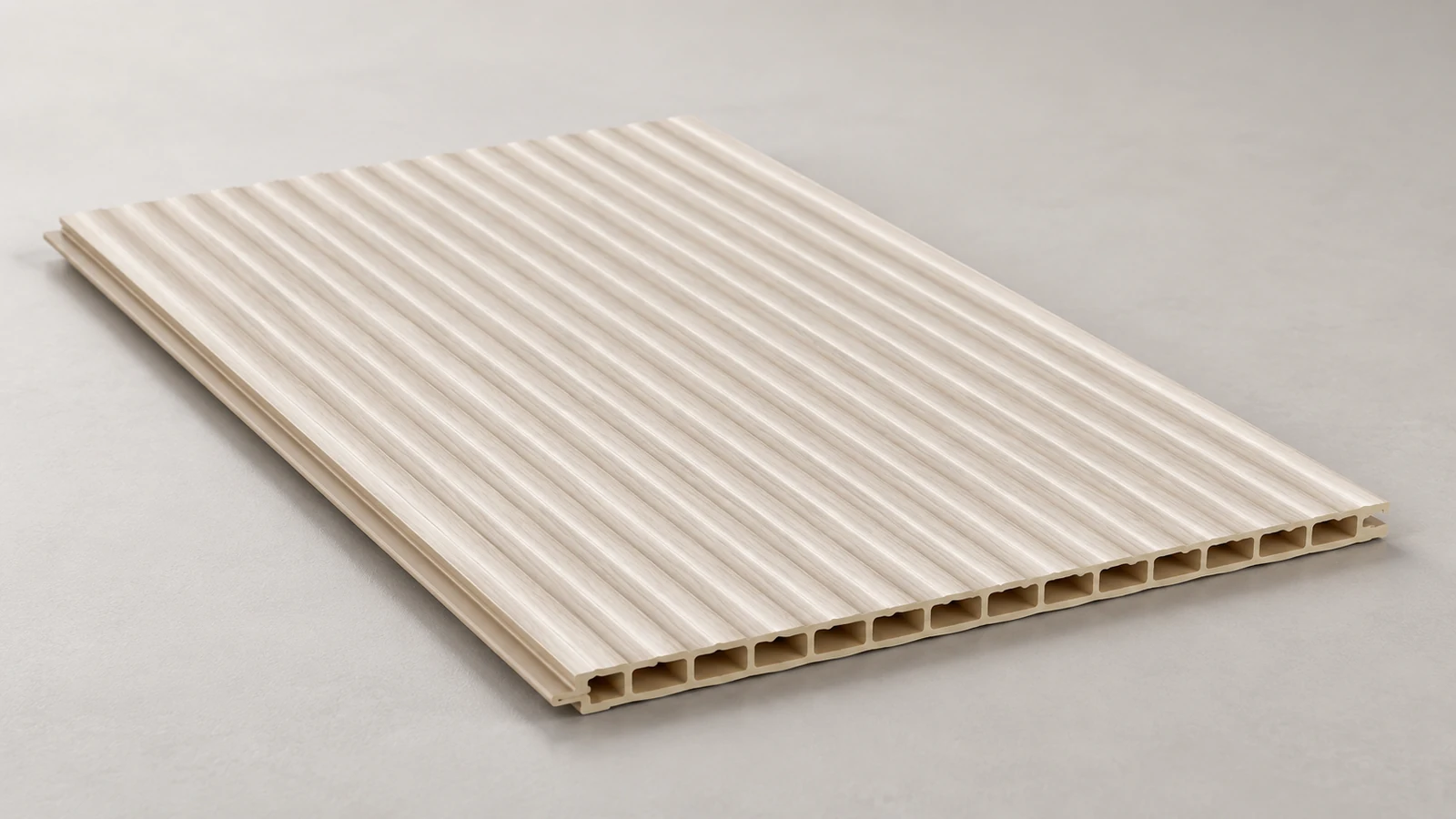
For a hollow WPC wall panel, the overall depth and the thickness of material around an individual cavity are different measurements. The section needs to distinguish the panel-back reference, the outermost decorative face, the recessed portions and the connecting edges. Measuring across one cavity wall cannot establish the overall projection, while measuring a raised crest alone says nothing about the local wall beneath it.
Dongfanglong’s 159 WPC Thin Fine-Wave Fluted Wall Panel is published as a 10mm profile with a fine-wave face, hollow construction, an interlocking joint and a thermally laminated surface. That identifies a specific product form, rather than a solid, uniformly thick sheet. Its published thickness still does not define the position of the panel after fixing it to a particular wall.
The drawing used for approval should mark where the nominal thickness is measured, whether the finished surface is included and what dimensional tolerance applies. These details are especially important when a trim or neighbouring finish leaves little spare room. A nominal dimension and an agreed maximum installed projection are two separate requirements.
Calculate WPC Wall Panel Installed Thickness from the Actual Build-Up
The wall build-up is the combination of preparation, backing, attachment and decorative material that establishes the final surface. To calculate its projection, use one reference plane throughout the detail. Otherwise, a dimension taken from the original wall can be mistakenly compared with one taken from a newly levelled backing.
Account for the Layers Behind the Panel
A useful geometric relationship is:
Finished panel projection = panel-back offset from the reference plane + profile depth from that same panel-back reference.
This is a way to read a section, not a product-specific installation formula. The panel-back offset comes from the actual arrangement behind the profile. A levelling layer, backing board or stand-off connection may contribute to it; a component recessed within another layer must not be counted twice. A trim that extends farther forward needs its own outermost-face check.
| Part of the detail | Dimension to establish | Why it affects the decision |
|---|---|---|
| Existing wall and preparation | Position of the prepared surface relative to the chosen reference plane | Levelling can move the base from which the new finish is set out. |
| Backing and fixing arrangement | Actual offset to the panel-back reference | A panel held away from the wall occupies more space than its profile depth alone. |
| Decorative profile | Distance from the panel-back reference to the outermost finished face | Raised portions, rather than groove bottoms, govern the maximum projection. |
| Edge or corner fitting | Outermost fitting position and panel-engagement geometry | The fitting may project beyond the field panel or require additional space for engagement. |
If a design allows only the same depth as the nominal 10mm panel, any positive offset behind that panel consumes space the design has not allowed for. Selecting a thin profile therefore does not remove the need to review the wall preparation and fixing detail.
Use Retained Door Frames and Cabinets as Control Points
Consider a renovation in which an existing door casing remains in place. If the new wall face projects beyond the casing, the planned edge relationship changes even though the correct panel has been delivered. A section through that junction exposes the problem before the whole wall is covered.
The decision is then specific: preserve the existing casing and revise the wall detail, change the transition, or select another suitable assembly. It is not simply “choose the thinnest panel.” Reducing the profile depth will not necessarily resolve an offset created mainly by the backing arrangement.
Thickness and flatness also require separate checks. A sample can meet its thickness requirement while a proposed installation still leaves the face misaligned with a retained cabinet. Review the permitted finished-face position at those interfaces, including the agreed product and installation allowances, rather than budgeting every component at its nominal value with no room for variation.
Plan 10mm WPC Wall Panel Installation Around Its Support Conditions
Compare the Cross-Section and Span, Not Thickness Alone
Two profiles with the same overall depth need not have the same response to loading. Material stiffness, cross-sectional geometry, unsupported span and support conditions all enter a bending assessment. The distinction is fundamental to structural mechanics; MIT’s 2.080J Structural Mechanics, Lecture 5: Solution Method for Beam Deflections treats material and sectional rigidity separately from loading and boundary conditions. It does not provide a capacity rating for a particular wall panel.
For procurement, the practical implication is to compare the section together with the intended support layout. A profile resting against a defined backing and one bridging between separated supports are not the same test arrangement. A result obtained on one cannot automatically describe the other.
Look for the loaded face, support locations, span, fixing arrangement and acceptance criterion in any relevant assessment. A short loose sample can reveal the cavities and finish, but bending it by hand does not establish an installation spacing. Neither a “10mm” label nor the word “hollow” provides a defensible ranking of strength or impact resistance.
An Interlocking Joint Is Not the Complete Wall Attachment
A panel-to-panel connection joins neighbouring pieces. A panel-to-wall attachment transfers the installed assembly to its supporting substrate. Even when a joint incorporates a fixing feature, the drawing must show how that feature connects to the wall. A description of interlocking assembly alone does not specify the adhesive, fastener, clip or backing system.
This distinction also returns to the thickness calculation. If a proposed attachment holds the panel farther from the substrate, the finished face moves outward. If the fixing sits within the profile, its position has to be read from the section rather than added as a separate full-thickness layer. Selecting the fixing method and calculating the projection are therefore linked decisions.
Do not use the decorative profile as the assumed support for a display, mirror or cabinet. A fixture requires an identified attachment and load path appropriate to that fixture. Its bracket may also need a coordinated detail where it meets the fluted face; the wall finish and the fixture support should not be treated as the same component.
Resolve WPC Wall Panel Edge Trim and Corner Details in Section
Match Trim Geometry to the Installed Profile
A trim labelled for a particular thickness is not enough to establish compatibility. The actual edge may contain an interlocking projection, a hollow opening or a cut through a raised flute. The fitting has to receive or cover that geometry while finishing at the intended face position.
The wall installation fittings category provides related profiles for the material-selection stage. Treat it as a range from which a coordinated combination can be developed, not as proof that every listed fitting mates with every wall panel.
| Interface | What a thickness-only check misses | What the combined section should resolve |
|---|---|---|
| Panel termination | The factory joint edge and a site-cut edge may have different geometry. | Which edge is being covered, the fitting’s engagement and the exposed finish. |
| Retained door casing | A panel can fit its trim while the whole assembly projects beyond the casing. | Panel and trim face positions measured from the same reference plane. |
| Internal or external corner | Nominal depth does not describe how the two faces and corner fitting meet. | The receiving space, coverage, fixing access and intended corner appearance. |
| Transition to another finish | A straight elevation does not show the step between the two finished faces. | The intended flush, recessed or projecting relationship and its termination detail. |
A cut can remove the original connecting edge. The resulting termination must therefore be reviewed as the edge that will actually be installed, rather than as an unchanged full-width panel. Similarly, a fitting that conceals an edge does not necessarily support or secure it. Coverage, engagement and attachment are separate functions.
Check Assembly Access and the Specified Movement Detail
A joint can look correct in its final position yet be difficult to assemble. Where the fitting goes in first, the panel needs the required approach and engagement space. Where a cover is added later, the detail must leave access for that operation. A trial using the intended sequence reveals restrictions that a finished photograph cannot show.
Any specified movement allowance must remain available after the panels and trims are assembled. Covering a joint is not the same as allowing it to move. The relevant gap and restraint details belong to the selected system and project conditions; there is no basis for assigning one universal clearance to every 10mm WPC profile.
Keep Performance Claims Separate from the 10mm Label
Define the Exposure, Not Just the Room Name
Interior WPC wall cladding should be selected for the actual exposure at the proposed position. A decorative feature wall and a surface receiving regular direct water contact present different questions, even when both are inside a building. A general moisture-resistance statement does not describe how joints, cut edges and penetrations manage water.
For a wet-area proposal, suitability would need to address the complete wall detail, not just the exposed panel face. Without that evidence, do not extend an interior decorative application into a shower-lining or waterproofing claim. The same principle applies when moving from indoor decoration to exterior exposure: a material name does not establish the new application.
Require Evidence That Identifies the Product and Assembly
Fire and emissions claims need to be tied to the product and assessment they describe. A report for a different profile, material formulation or finish is not automatically evidence for the selected 10mm panel. The relevant review identifies the tested product, specimen construction, thickness, finish, test method, result and stated application limits. Where mounting or backing is part of the assessment, it also needs to correspond to the proposed use.
There is a useful distinction in BSI’s published description of BS EN 15534-5:2014, Specifications for cladding profiles and tiles: it covers WPC cladding products for internal or external use, but excludes support rails, cover strips and fastener devices. A product assessment therefore should not be mistaken for validation of every accessory and attachment in a wall assembly.
That standard reference is not a claim that this panel is certified to it, or that it is required for every project. Establish the applicable project requirements first, then assess the matching evidence. Nominal thickness cannot supply a fire classification, emissions result or approved fixing-system performance.
Approve a Panel-and-Trim Mock-Up Before Ordering
A colour chip answers a finish question. A coordinated mock-up can answer whether the selected profile, backing and fittings produce the required wall detail. Include neighbouring panels, a relevant termination or corner, and the retained frame or adjoining finish that sets the projection limit. Reproduce the proposed backing and fixing arrangement rather than pressing the sample directly against a wall for convenience.
Measure the installed face from the agreed reference plane. Check whether the trim receives the actual edge, whether adjacent pieces engage as intended and whether the installation sequence remains possible. Examine the result with the project’s intended finish sample. A successful loose-panel comparison is not enough when the buying decision depends on the complete junction.
Record what the mock-up demonstrates and what it does not. It can establish fit, finish relationships and practical assembly access; it does not replace a fire, emissions or mechanical test. If the backing, fixing or trim changes after approval, revisit the affected dimensions and interfaces instead of assuming the original sample still represents the order.
For the inquiry, connect the product requirement to the site constraint: give the exact panel and finish reference, the wall section and retained interfaces, the existing substrate condition, the maximum permitted projection, the exposure and the purchase quantity. The allowable projection explains why a 10mm profile is being considered; the section explains what else must fit around it.
The quotation should then identify the offered panel, included fittings, installation-detail references and any departures from the proposed assembly. Separate material supply from site preparation or installation work so that responsibility for the backing and finished-face position is clear.
Use the Dongfanglong project inquiry form to share the panel reference, section details and required quantities. The purchasing decision is a panel-and-installation combination that fits the intended wall—not a nominal thickness considered on its own.